Modal and Harmonic Analysis of a Langevin-Type Ultrasonic Transducer Using Full 3D Finite Element Modeling
Ultrasonic transducers play a critical role in applications such as structural health monitoring, industrial cleaning, welding, medical imaging, and distance measurement.
Among various designs, the Langevin-type sandwich transducer is widely recognized for its strong electromechanical efficiency and robust resonance behavior.
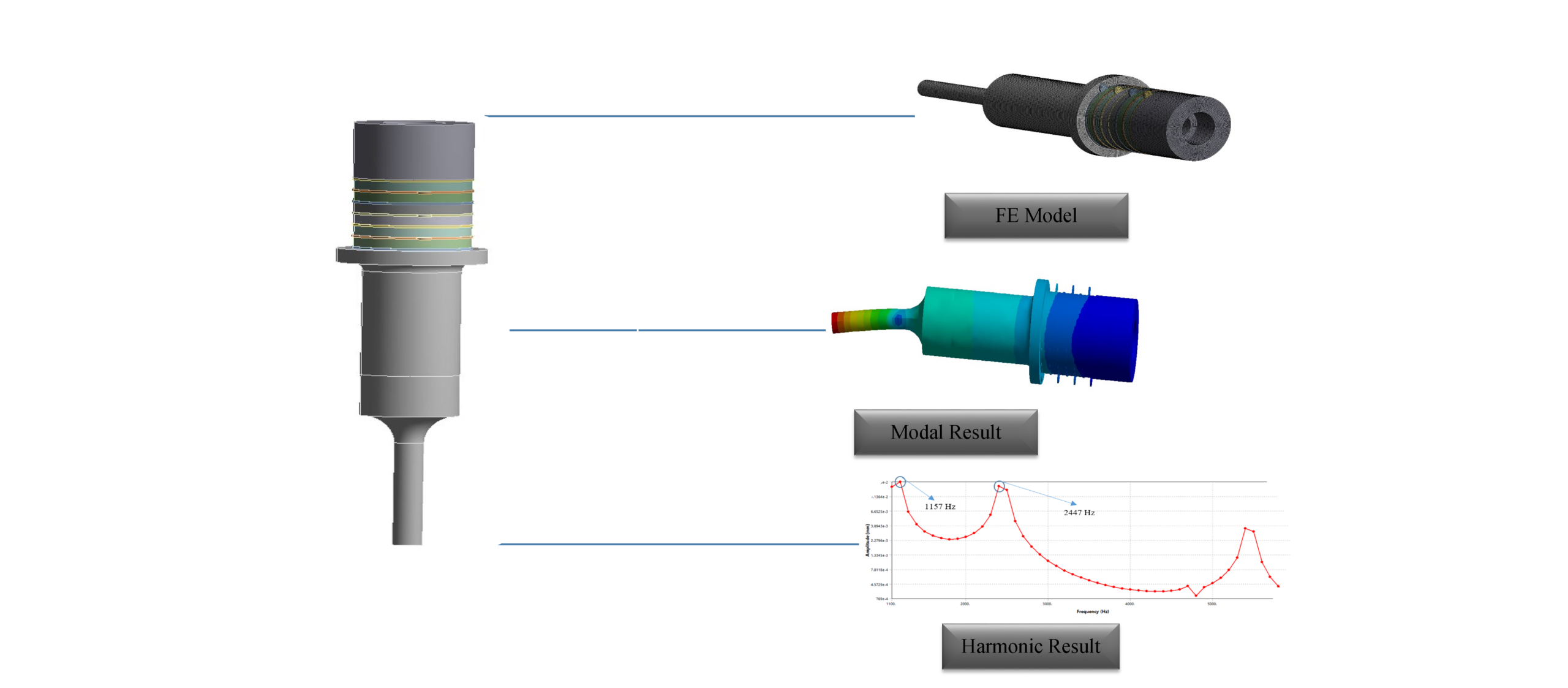
In this study, a complete three-dimensional finite element model of a Langevin transducer was developed. The objectives were to extract its natural frequencies, evaluate harmonic response under electrical excitation, and characterize the dynamic behavior for future tuning and optimization.

Key Factors Analyzed during FE Simulations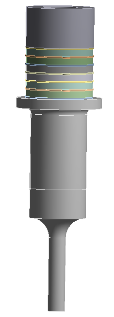
-
Identification of bending, mixed bending–compression, axial, and rotational modes
-
Full electromechanical coupling of the piezoelectric stack
-
Harmonic response evaluation using the full 3D model
-
Correlation between modal frequencies and harmonic amplitude peaks
-
Effects of clamped installation on mode shapes
-
Visualization of bending and rotational behavior across lateral directions
Project Highlights
-
Geometry: Full 3D Langevin-type structure
-
Material: Complete piezoelectric electromechanical definition
-
Analysis Types: Modal + Harmonic
-
Boundary Condition: Fully fixed at the top surface
-
Excitation: Electrical voltage applied on electrode faces
-
Modeling Approach: Full geometry used for both modal and harmonic analysis
-
Goal: Dynamic characterization, validation, and performance assessment

FE Analysis Tips and Tricks
-
Use coupled-field solid elements to ensure correct electromechanical behavior.
-
Apply bonded contacts throughout the piezo–metal interfaces for realistic stress transfer.
-
Refine mesh in the piezoelectric region; ultrasonic systems are highly mesh-sensitive.
-
Always perform harmonic analysis on the full model to maintain correct stiffness path and dynamic response.
-
Clamped boundary conditions significantly modify the modal landscape — ensure they reflect actual mounting conditions.
-
A fine frequency resolution near expected peaks improves harmonic accuracy.
Material Selection
The piezoelectric disk stack was assigned a complete set of electromechanical properties including:
-
Elastic stiffness matrix
-
Piezoelectric coupling matrix
-
Relative permittivity tensor
-
Density and damping
Metallic front and back masses were modeled using standard linear elastic properties.
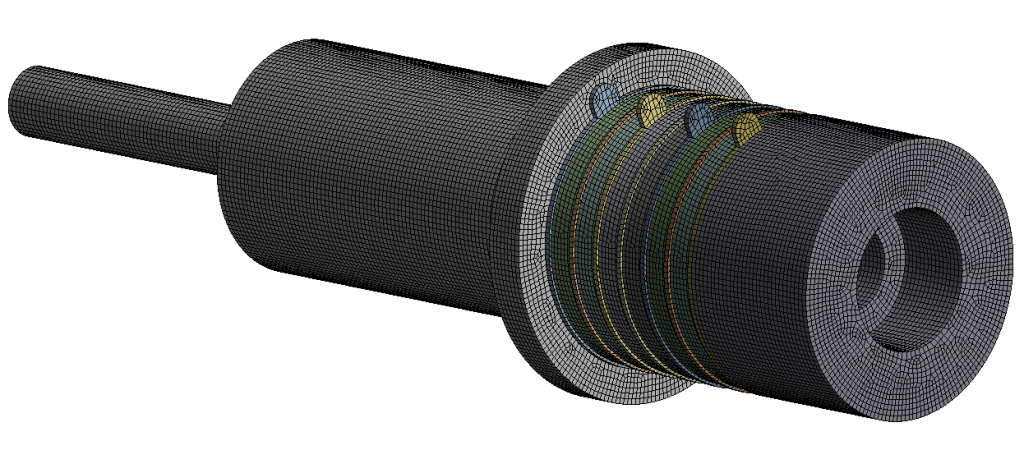
Geometry and Mesh Generation
The transducer model included:
-
Front mass
-
Back mass
-
Piezoelectric stack
-
Central bolt
-
Electrode layers
A tetrahedral mesh with local refinement ensured high accuracy in deformation and wave propagation prediction.
Boundary Conditions
-
Full fixation on the top surface, representing the real clamped installation
-
Electrical potential applied to piezoelectric disks during harmonic response
-
Bonded mechanical interfaces across all assembly components
Analysis Settings
Modal Analysis
-
Extraction of natural frequencies up to ~6 kHz
-
Identification of bending, axial, and rotational modes
Harmonic Analysis
-
Full transducer model used
-
Voltage-driven excitation
-
Frequency sweep across the same range
-
Displacement amplitudes captured in both lateral and longitudinal directions
Results Interpretation
Modal Results
The first structural modes appeared at the following frequencies:
-
1153.5 Hz
-
1154.3 Hz
-
2447 Hz
-
2457.3 Hz
-
4762 Hz
-
5448.2 Hz
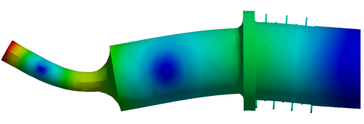
These frequencies correspond to:
-
Bending-dominated modes in the lateral directions
-
Mixed bending–compression shapes
-
Higher-order bending patterns
-
Rotational modes around the longitudinal axis, which naturally appear in clamped transducer structures
Harmonic Response Results
Using the full 3D model, the harmonic frequency sweep revealed displacement peaks at approximately: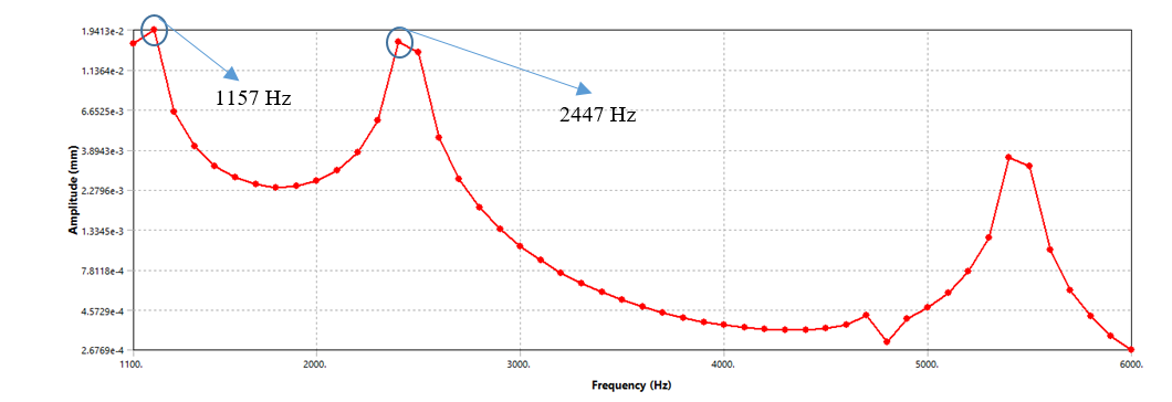
-
~1200 Hz
-
~2400–2500 Hz
-
~5400–5500 Hz
These peaks align with the modal frequencies and reflect lateral bending modes, higher-order bending effects, and slight rotational coupling around the transducer’s longitudinal axis.
The longitudinal deformation remained limited due to the clamped boundary condition, which suppresses high-frequency axial resonance.
Engineering Insights
-
When the transducer is clamped, bending modes dominate the dynamic behavior, and classic longitudinal ultrasonic resonance does not appear in the operating range.
-
Harmonic amplitude peaks matching modal frequencies confirm correct material definition and model fidelity.
-
Rotational modes around the main axis emerge naturally due to asymmetry in clamped conditions and should be considered during design tuning.
-
Using the full model avoids artificial symmetry constraints and provides realistic predictions of both bending and rotational behavior.
-
This simulation workflow is suitable for optimizing resonance performance, improving mechanical robustness, and designing tailored frequency responses.
Conclusions
- A complete 3D electromechanical model of the Langevin-type transducer was successfully developed.
- Modal analysis revealed bending, mixed bending, and rotational modes in the 1–6 kHz range.
- Harmonic analysis using the full model produced amplitude peaks aligned with modal frequencies, confirming model accuracy.
- The clamped installation condition significantly shifts dynamic behavior toward lateral and rotational modes.
- This validated modeling framework provides a reliable foundation for future transducer optimization and resonance tuning.