Static and Fatigue Assessment of Metro Car Handrails
31 May 2026
Analysis

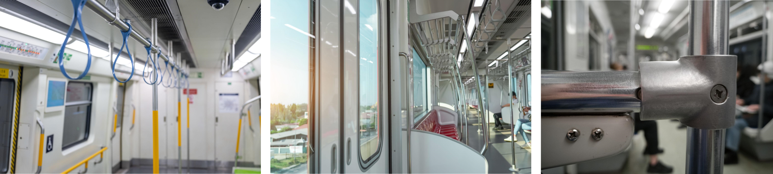
This study focuses on evaluating the static performance and fatigue endurance of various handrail and grab pole designs installed in metro train cars. Due to modern demands for lightweight design, a reduced thickness was proposed for handrail components. The challenge was to validate whether this design could still comply with EN 12663-1 and VDI 2230 standards under service and dynamic loading.

Key Parameters and Handrail Types
The study included the following configurations:
- Six-seat, Three-seat, Two-seat handrails
- Roof-mounted and Vertical grab poles
Each handrail was subjected to vertical, lateral, longitudinal, and combined loads based on standard guidelines.

Project Highlights
- Load magnitudes:
- Vertical: 1000 N
- Lateral / Longitudinal: 850 N
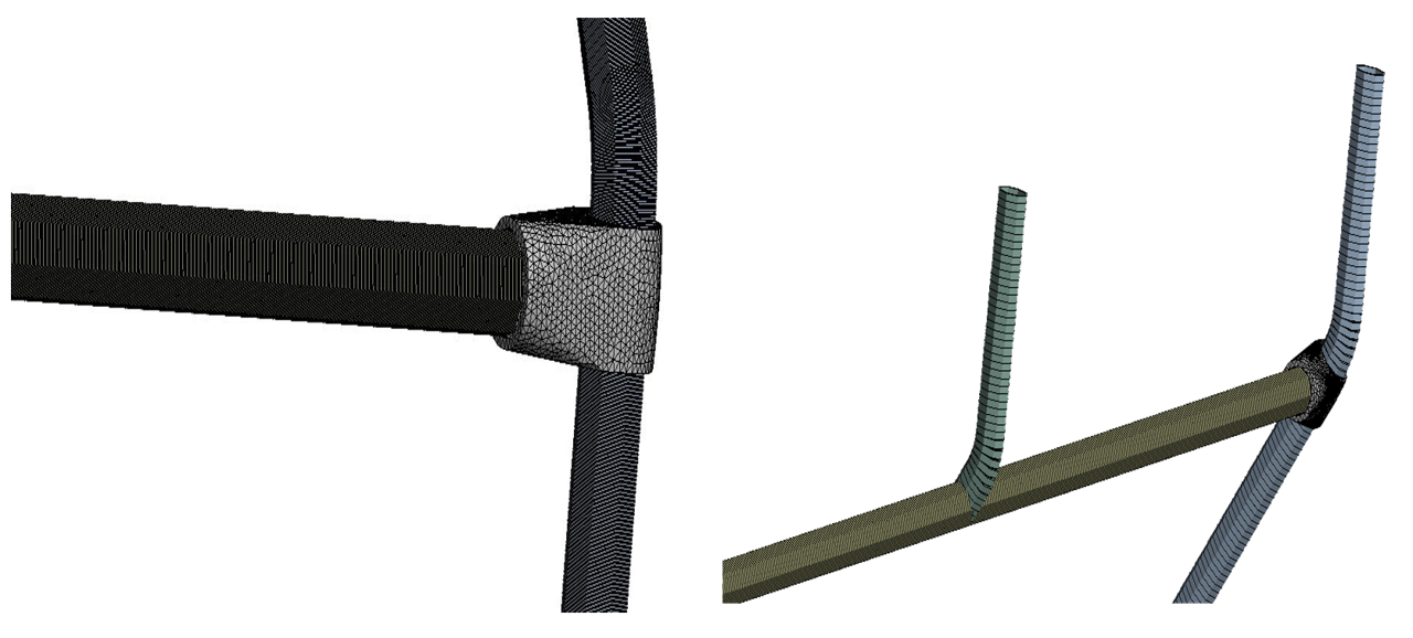
- Geometry modeled in ANSYS with Shell181 (panels) and Beam188 (tubes)
- Bolts simulated using fixed joints with preload from VDI 2230
- Fatigue checked using Goodman-Smith Diagram
- Mesh convergence confirmed (<1% variation)

FE Analysis Tips and Tricks
- Welds and bolt holes require local mesh refinement
- Bolts should be modeled with preload per VDI 2230
- Supports: pinned/roller boundaries mimic real constraints
- Consider combined loading scenarios for worst-case stress
Material Selection
| Component | Material | E (MPa) | Yield (MPa) |
|---|---|---|---|
| Handrail | SUS304 | 200,000 | 550 |
| Roof Panel | AlMgSi(B) | 70,000 | 215 |
| Bolt (M8x25, 8.8) | Steel 8.8 | 210,000 | 640 |
Geometry Editing
- All five handrail types modeled individually
- Bolt connection zones retained for stress concentration tracking
- Reduced thickness applied per latest design
Mesh Generation
| Mesh Type | Elements | Max Stress (MPa) |
|---|---|---|
| Coarse | 244,682 | 89.19 |
| Medium | 268,931 | 89.65 |
| Fine | 307,546 | 90.09 |
Analysis Settings
- Solver: Static structural and fatigue assessment
- Loads applied at center span of each handrail
- Load combinations per EN 12663-1 guidelines
Connection Types
- Bolts modeled using fixed joints (no slip)
- Welded seams assumed fully bonded
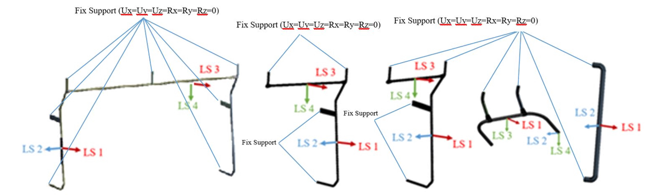
Boundary Conditions
- Simply supported (pinned and roller) constraints
- All load directions tested independently and combined
Load Conditions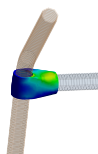
- LC1: Vertical → 1000 N
- LC2: Longitudinal → 850 N
- LC3: Lateral → 850 N
- LC4: Combined load (multi-axial)
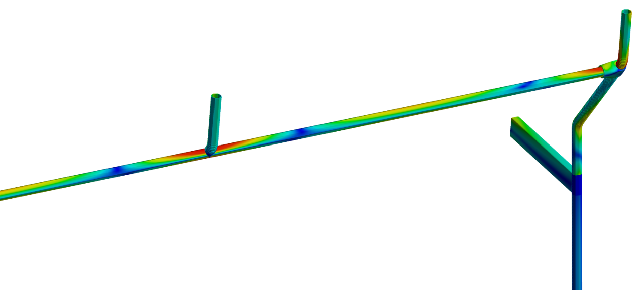
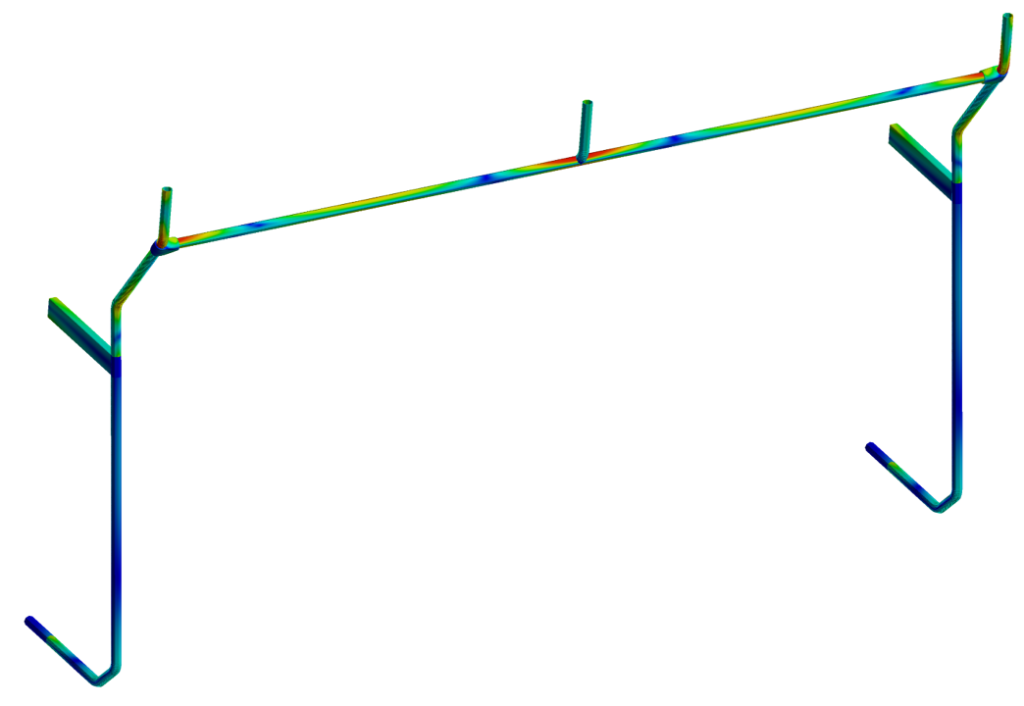
Results Interpretation
- All handrail types passed the static stress check
- Stress values below allowable for SUS304 and AlMgSi(B)
- Bolt loads remained under critical thresholds (<122 N)
- Fatigue life exceeded 10⁷ cycles in all models
- Safety factor >1.15 confirmed per EN 12663-1
Summary
This project confirms:
- Even reduced-thickness handrails meet required safety criteria
- Fatigue and static performance validated using conservative assumptions
- Bolted and welded connections performed reliably under load
- ANSYS and MDESIGN tools successfully integrated for validation