Flexural Analysis of Reinforced Concrete Beams with Pre-Existing Damage and Composite Strengthening
This study investigates the flexural performance of reinforced concrete (RC) beams under four-point bending conditions. The focus is on evaluating how pre-existing internal damages and the application of external composite strengthening (CFRP laminates) affect structural behavior.
The tested beams fall into three major categories:
- Control beam (CB) without damage
- Beams with internal pre-cracks or rebar damage
- Damaged beams strengthened with externally bonded FRP laminates
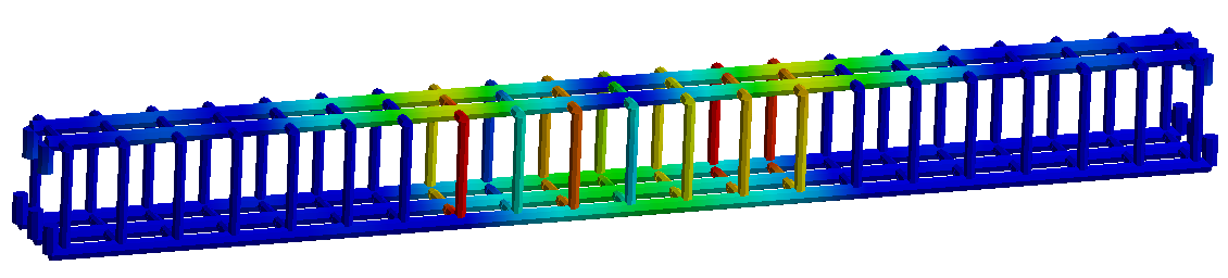
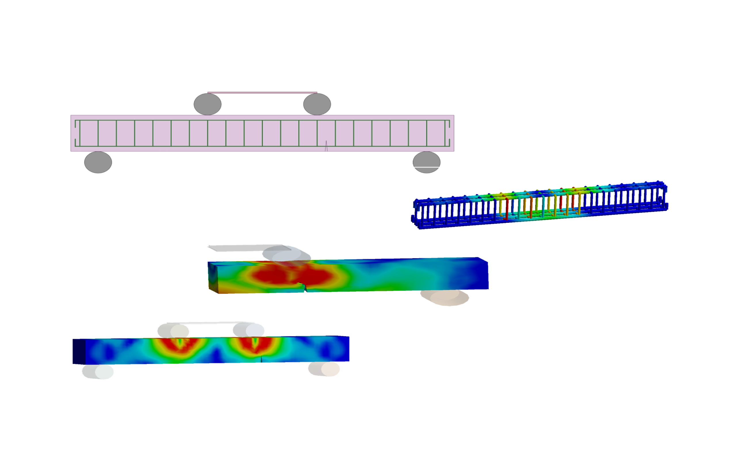
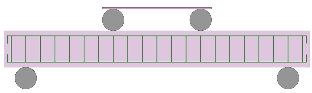
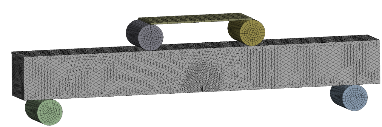
Each beam had a cross section of 25×25 cm and a clear span of 180 cm. Loading was applied through a four-point bending configuration.

Damage Scenarios and Beam Identification
Based on the classification in the original study (as defined in experimental setup and material datasheets):
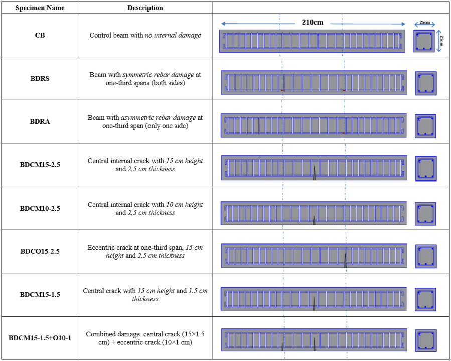
Each crack was pre-defined by inserting voids or initiating cracks to simulate field-like degradation.

Project Highlights
- Concrete grade: C25 (f’c = 25 MPa) (as defined in experimental setup and material datasheets)
- Longitudinal reinforcement: ϕ10 (4 bars) and ϕ14 (2 bars)
- Shear reinforcement: ϕ10 stirrups at 16 cm spacing
- Effective beam span: 180 cm
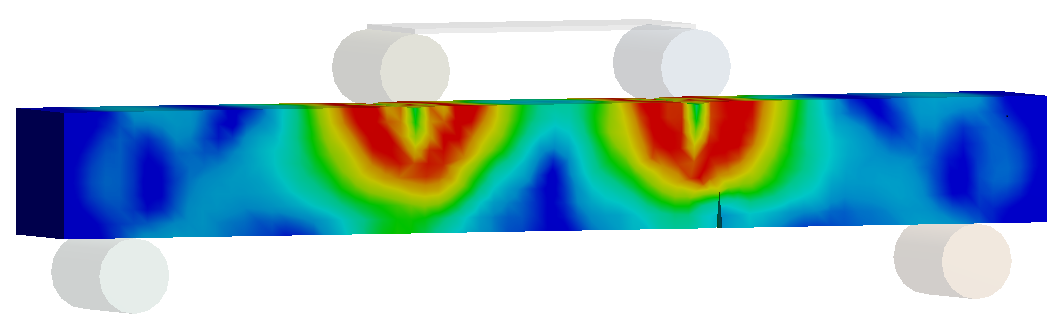
- Failure in unstrengthened beams generally occurred at or near pre-damaged zones
After experimental damage characterization, several beams were retrofitted with externally bonded CFRP laminates.

FE Analysis Tips and Tricks
- Damage zones modeled explicitly using cut or weakened regions
- Shell elements and solid modeling hybrid used to simulate cracks
- Interface contact behavior (for FRP debonding) should be carefully tuned
- Experimental deflection results were used to calibrate numerical models
Material Selection
• Concrete (C25):
- f’c = 25 MPa, E = 27.4 GPa, ν = 0.2, Density = 2400 kg/m³
• Reinforcing Steel:
- fᵧ = 422 MPa (longitudinal), 430 MPa (stirrups)
- E = 200 GPa, ν = 0.3, Density = 7850 kg/m³
• CFRP – Epoxy Carbon UD Prepreg:
- E₁ = 200 GPa, E₂ = 8.6 GPa, ν₁₂ = 0.27, G₁₂ = 4.7 GPa
- Tensile strength: 4.95 GPa (fiber), 29 MPa (transverse)
- Shear strength: 60 MPa (XY/XZ), 32 MPa (YZ)
- Interface weakening factor: 0.8
Geometry Editing
- Beam size: 25 cm × 25 cm cross-section, 210 cm span
- Strengthening with 1 or more CFRP layers on tension face only
- CFRP layer width = 8 cm, spacing = 7 cm
- Applied on beams with damage in mid-span, third-span, or combined
Mesh Generation
- Element size: Refined near damage zones
- Explicit Dynamic solver used to capture post-peak and failure behavior
- Reinforcement bars modeled using Line Body elements and embedded in concrete
- Numerical results validated using peak load and crack pattern comparison
Analysis Settings
- Explicit dynamic simulation to capture post-cracking behavior
- Load applied gradually through two concentrated points
- Supports modeled as pinned and roller
Connection Types
- Rebars fully embedded (no slip)
- CFRP–concrete interface modeled using bonded contact (no slip allowed)
Boundary Conditions
- Simply supported setup
- Supports: pinned and roller
- CFRP applied only to tension face
Load Conditions
- Four-point bending
- Load introduced symmetrically across central region
🔄 Results Interpretation
Experimental vs. FEM Results – With and Without Composite (CFRP)
| Specimen | Experimental (No CFRP) | FEM (No CFRP) | Error % | Experimental (CFRP) | FEM (CFRP) | Error % |
|---|---|---|---|---|---|---|
| CB (Control) | 61.5 | 57.6 | 6.3% | 75.0 | 64.6 | 13.8% |
| BDRS | 22.5 | 25.7 | 14.2% | 80.0 | 81.9 | 2.3% |
| BDRA | 16.5 | 19.0 | 15.2% | 70.0 | 62.0 | 11.4% |
| BDCM15-2.5 | 41.5 | 39.9 | 3.9% | 71.0 | 66.0 | 7.1% |
| BDCM10-2.5 | 27.5 | 30.2 | 9.8% | 80.0 | 71.5 | 10.6% |
| BDCO15-2.5 | 54.0 | 52.3 | 3.2% | 82.0 | 73.7 | 10.2% |
| BDCM15-1.5 | 33.5 | 33.5 | 0.1% | 75.0 | 71.6 | 4.5% |
| BDCM15-1.5+O10-1 | 42.5 | 41.1 | 3.4% | 61.0 | 68.8 | 12.7% |
🔍 Interpretation Highlights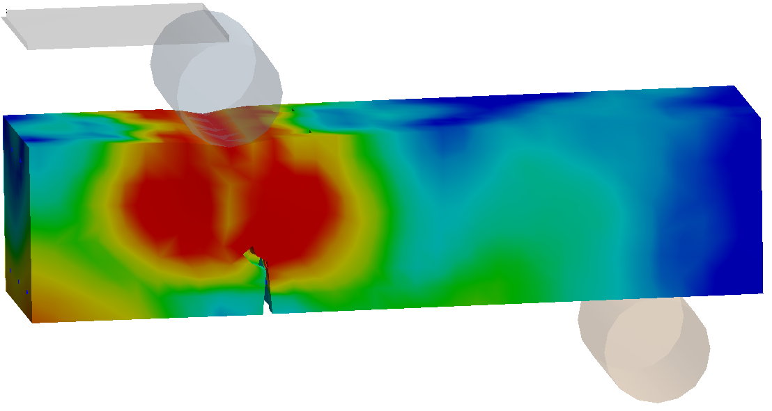
- Best FEM Accuracy (No CFRP): BDCM15-1.5 (0.1% error)
- Best FEM Accuracy (With CFRP): BDRS (2.3% error)
- Worst FEM Prediction (With CFRP): BDCM15-1.5+O10-1 (12.7% error)
- Trend: CFRP strengthening generally improves agreement in beams with symmetrical or controlled damage. In complex or combined damage, deviation may increase due to nonlinear effects or modeling assumptions.
The results compared experimental peak load vs. FEA for each beam:
- Error without CFRP was highest for severely damaged beams (up to ~15%)
- Strengthening with CFRP reduced the relative error significantly (most below 7%)
- Beams with dual damage zones benefitted most from FRP wrapping
The analysis demonstrated that using CFRP can effectively compensate for internal damage and restore or exceed original flexural capacity.
📊 Summary
This project confirms that:
- Accurate modeling of internal damage is critical for flexural FEA
- External CFRP retrofit significantly improves accuracy and performance
- Layer width, spacing, and fiber properties must be aligned with manufacturer guidelines
By combining experimental setups with calibrated FE models, engineers can reliably simulate and optimize real-world RC beam retrofitting scenarios.