FEA-Based Strength, Fatigue, and Modal Validation of Railway Gangways
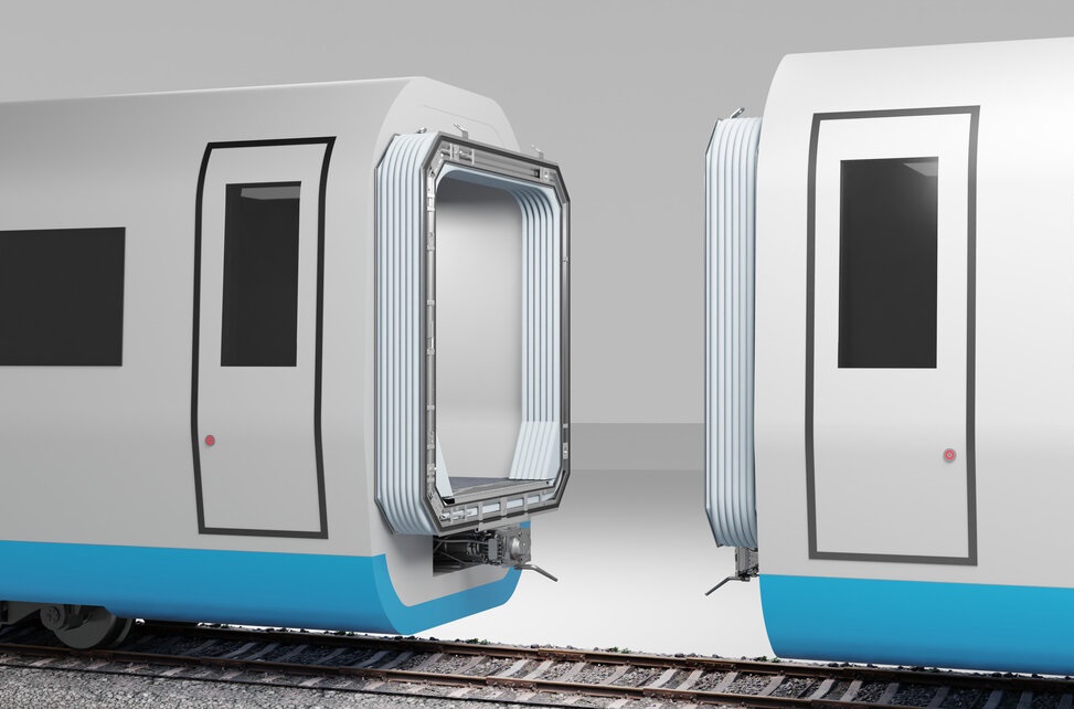
A gangway is a critical interface between connected railcars, responsible for ensuring safe and stable passage for passengers under varying operational loads. This article discusses how advanced Finite Element Analysis (FEA) was used to validate a gangway system’s structural strength, fatigue life, modal performance, and bolt integrity, all in accordance with railway industry standards.
Finite Element Analysis: A Powerful Tool for Structural and Fatigue Validation of Rail Gangways
Finite Element Analysis was used to evaluate the gangway’s performance under multiple conditions, including static loads, operational vibrations, and repeated dynamic stresses. This approach enabled accurate prediction of: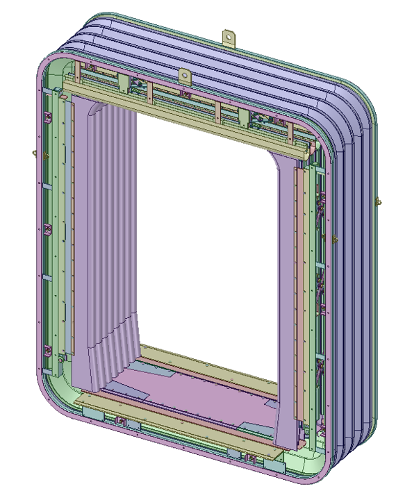
- Peak stresses under extreme static loads
- Fatigue life under cyclic train accelerations
- Natural frequencies to prevent resonance
- Bolt strength and preload validation
- Compliance with EN 16286-1:2013 and EN 12663-1:2010
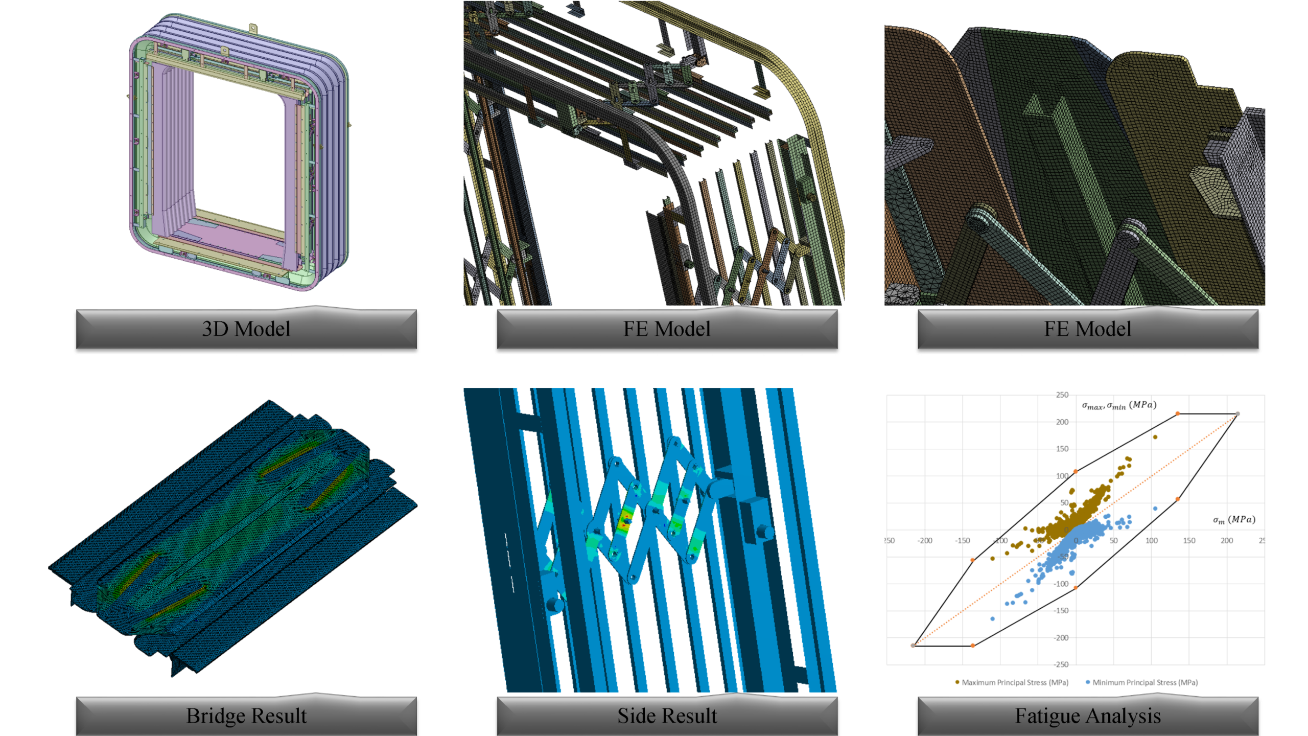
A critical step in our process was to first analyze the entire structure using FEM to identify the most critical stress locations. These locations were then instrumented with strain gauges, and physical testing was carried out to capture real-world stress data. This combined simulation-experimental approach ensured high confidence in the results and full validation of the FEM model, confirming the gangway design is safe for operational use.

Key Factors Analyzed During FE Simulations Include
- Static loading on the bridge and sidewall assemblies
- Fatigue assessment using Goodman-Smith diagrams under dynamic conditions
- Modal analysis to evaluate vibration modes and avoid resonance
- Bolt analysis under vertical, longitudinal, and lateral accelerations
- Comparison of FEM and physical test data to ensure model accuracy
![]()
Project Highlights
| Feature | Details |
| Structure | Gangway assembly (bridge, sidewalls, bellow, step plates) |
| Standards | EN 16286-1:2013, EN 12663-1:2010 |
| Tools Used | Finite Element Method (Static, Modal, Fatigue, Bolt Analysis) |
| Physical Validation | Strain gauge testing at critical stress locations |
| Conclusion | Design verified, compliant with safety, strength, and fatigue limits |

FE Analysis Tips and Tricks
Careful setup of the FEM model is essential for accurate results and correlation with test data. Below are critical areas to focus on during the simulation process.
- Material Selection
| Property | Value |
| Density | 7750 kg/m³ |
| Young’s Modulus | 200,000 MPa |
| Poisson’s Ratio | 0.3 |
| Yield Strength | 215 MPa |
Tip: Use fatigue-safe stress limits based on material S-N curves and validated design codes (EN 12663).
- Geometry Editing
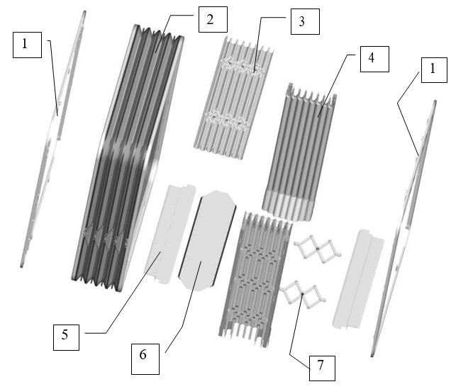
| Component No. | Description |
| 1 | VMP assembly |
| 2 | Bellow assembly |
| 3 | Ceiling bellow assymbly |
| 4 | Side protective bellow assembly |
| 5 | Step plate assembly |
| 6 | Bridge plate assembly |
| 7 | Bridge plate connection rod assembly |
Tip: Remove non-load-bearing details while retaining geometry affecting stiffness and local stress concentration.
- Mesh Generation
- Hex or tet elements depending on geometry complexity
- Local refinement around bolts, corners, and load interfaces
- Mesh convergence study performed

Tip: Aim for at least three elements through thickness in critical regions for accurate stress gradients.
- Analysis Settings
Static Load Cases:
| Load Case | Description | Load (N) | Application Area (mm) |
| LC1 | Vertical load on bridge | 800 | 100 × 200 |
| LC2 | Local horizontal load on wall | 120 | 100 × 100 |
| LC3 | Distributed horizontal load | 800 | 500 × 200 (at 1.3 m height) |
- Connection Types
M6 bolts (Yield Strength: 450 MPa, Allowable Load: 10.5 kN) were checked under multiple load orientations.
Bolt Load Cases:
| Load Case | Description | Result (kN) | Status |
| Bolt LC1 | Vertical (center-loaded) | 7.2 | Within limits |
| Bolt LC2 | Vertical (end-loaded) | 9.8 | Within limits |
| Bolt LC3 | Longitudinal acceleration (train stop) | 6.3 | Within limits |
| Bolt LC4 | Lateral acceleration (turning) | 5.9 | Within limits |
Tip: Include preload effects where relevant, especially for dynamic cases.
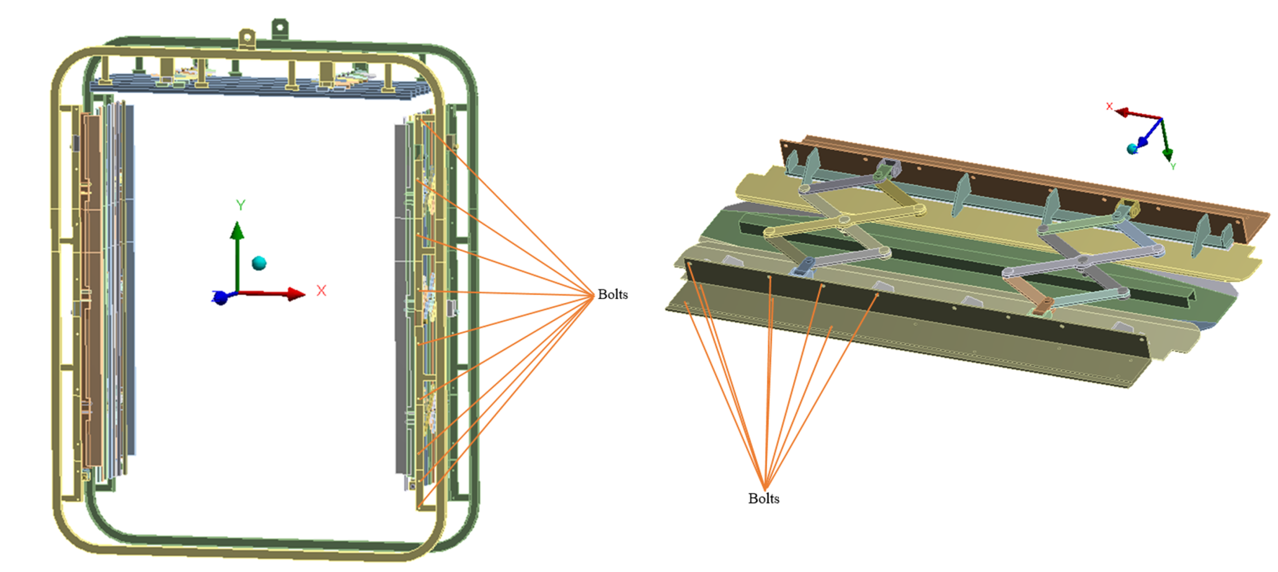
- Boundary Conditions
- Fixed supports applied at carbody frame interface
- Load applied via force or pressure over defined contact areas
- Symmetry applied to reduce model size where applicable
Tip: Validate support assumptions against actual mounting conditions to avoid unrealistic constraint-induced stresses.
Results Interpretation
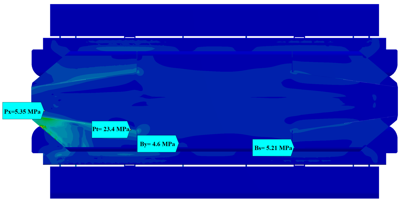
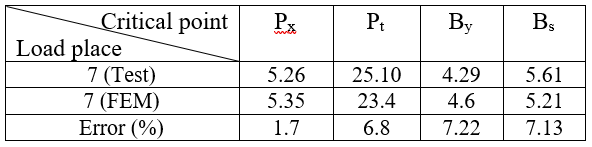
Static Strength
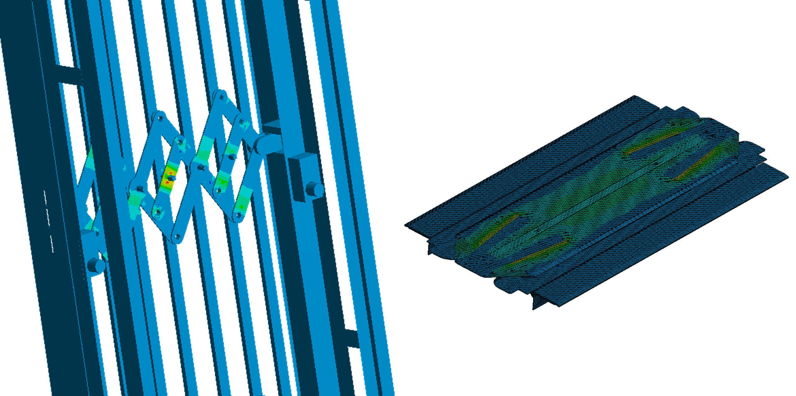
The maximum equivalent stress in the bridge under Load Case 7 is presented below, along with the corresponding strain gauge test results. The deviation between the FEM and experimental data is less than 10%, demonstrating a high level of correlation. This accuracy was achieved by first identifying critical stress zones using FEM and then strategically placing strain gauges for experimental validation.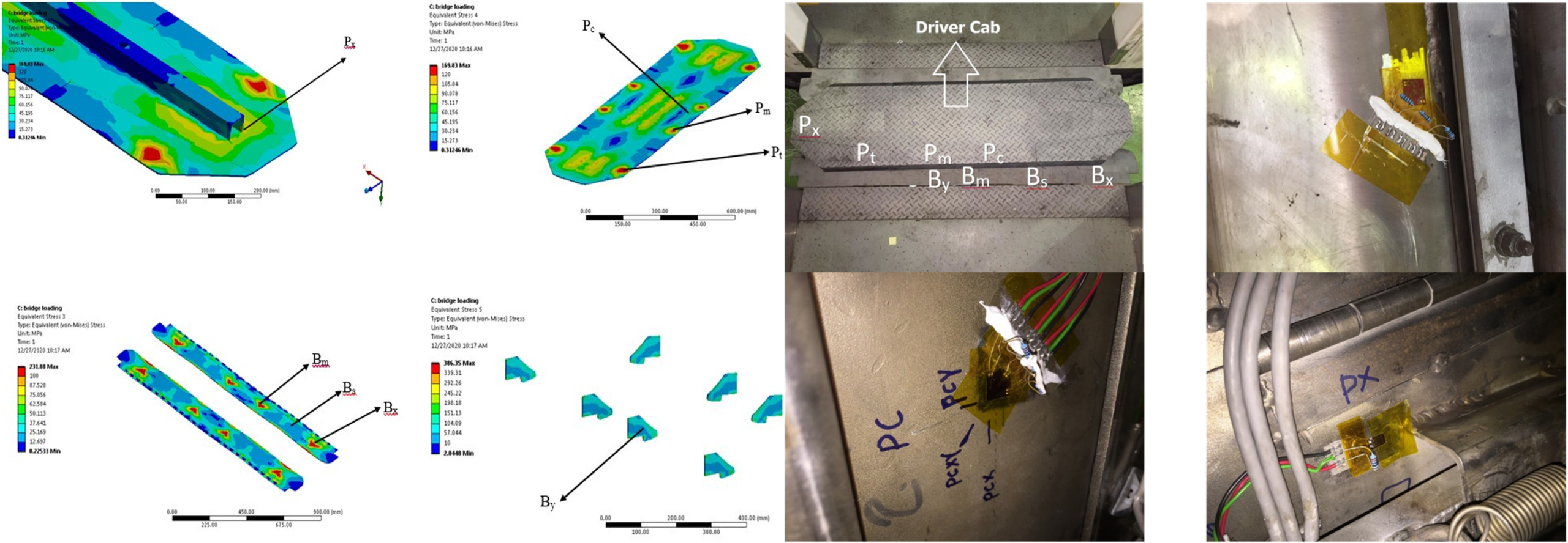
Fatigue Life
Fatigue life was evaluated under typical operational dynamics using Goodman-Smith criteria.
| Load Case | Direction | Applied Scenario | Status |
| Fatigue LC1 | Vertical | Passenger load cycles | Passed |
| Fatigue LC2 | Longitudinal | Acceleration/deceleration | Passed |
| Fatigue LC3 | Lateral | Curved track motion | Passed (critical) |
The vertical case on the bridge plate was found most critical but still within acceptable fatigue life per EN 12663.
Modal Analysis
Modal frequencies confirmed the system is safe from resonance:
| Mode | Bridge (Hz) | Sidewall (Hz) |
| 1 | 133.73 | 44.88 |
| 2 | 150.46 | 44.88 |
| 3 | 161.45 | 51.46 |
| 4 | 163.49 | 51.53 |
Conclusion
The gangway system meets all strength, fatigue, and vibration criteria under real-world rail conditions. The combination of high-fidelity simulation and physical validation ensures design safety, reliability, and compliance with industry standards.