Static, Modal, and Fatigue Analysis of a High-Side Freight Wagon

Freight wagons are the backbone of heavy rail transport, responsible for carrying large volumes of materials and goods across long distances under demanding service conditions.
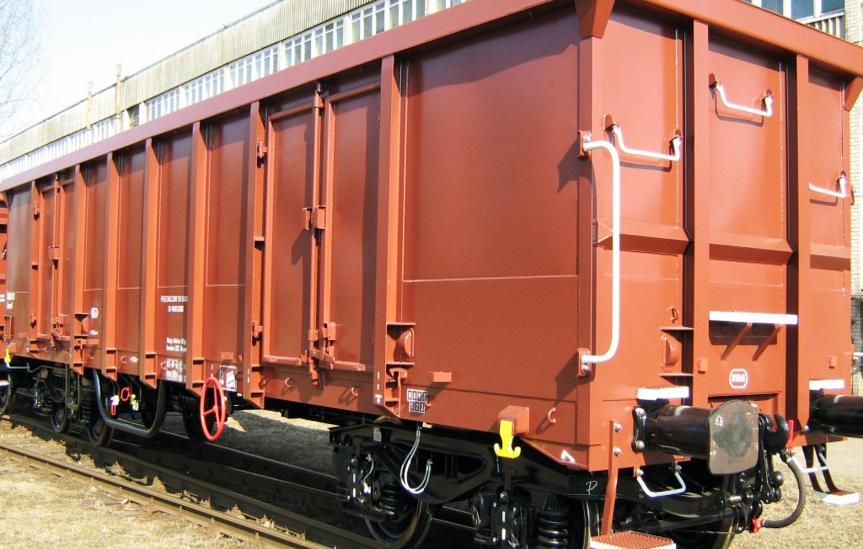
This study focuses on a high-side freight wagon, designed to withstand demanding operational loads while maintaining structural integrity and long-term durability.
To ensure its structural safety and performance, the wagon carbody was evaluated through static strength, modal, and fatigue analyses, following the international standards:
-
EN 12663-2:2010 – Structural requirements of railway vehicle bodies (Part 2: Freight wagons)
-
EN 15663:2009 – Definition of vehicle reference masses
These analyses verified that the structure withstands all prescribed loads, achieves the required stiffness, and maintains fatigue life above 10⁷ cycles. Additionally, strain gauge locations were proposed to support physical testing and validation.

Key Factors Analyzed during FE Simulations
-
Structural verification under static, modal, and fatigue conditions.
-
Compliance with EN 12663-2 acceptance criteria for safety and deformation.
-
18 static load cases covering all operating, extreme, and lifting conditions.
-
Modal analysis to determine the first ten natural frequencies and validate stiffness.
-
Fatigue assessment under lateral, vertical, and combined loading.

Project Highlights
-
Software used: ANSYS (commercial FEA package)
-
Structure type: Welded steel (St52) with bolted equipment connections
-
Total structural weight: 10,060 kg
-
Mesh size: ~211,900 shell elements and ~234,000 nodes
-
Average mesh skewness: 0.051 → excellent quality
-
Element type: Shell181 (suitable for thin-walled, welded assemblies)
-
Material properties:
-
Density: 7.8×10³ kg/m³
-
Young’s modulus: 2.1×10⁵ MPa
-
Poisson’s ratio: 0.3
-
Yield strength: 355 MPa
-
Ultimate strength: 520 MPa
-
-
Safety factor (EN 12663): 1.15 minimum

FE Analysis Tips and Tricks
-
Node coincidence was used to simulate welded joints accurately and transfer stresses between connected plates.
-
Distributed equipment masses were added at the floor to represent realistic loading conditions.
-
Mesh refinement was applied at buffer and coupler interfaces where stress gradients are highest.
-
Elastic supports modeled the bogie–carbody interaction.
-
Acceptance ensured that no permanent deformation occurred and that stresses remained below the allowable yield limit divided by the safety factor.
Material Selection
The wagon structure is composed entirely of St52 structural steel, selected for its balance of strength, ductility, and weldability.
According to EN 12663-2, the fatigue limit for this material in welded structures is approximately 186 MPa, which was used as the criterion for life prediction.
Geometry Editing
The finite element model represented the full carbody, including:
-
Underframe, sidewalls, and end walls (high-side configuration)
-
Coupler and buffer housings
-
Lifting brackets and reinforcement ribs
-
Cross beams and floor panels

The coordinate system was defined as:
-
X-axis: Longitudinal (buffer to buffer)
-
Y-axis: Lateral (side to side)
-
Z-axis: Vertical (track to roof)

Mesh Generation
| Parameter | Value / Description |
|---|---|
| Element type | Shell181 (4-node, reduced integration) |
| Total elements | ~211,900 |
| Nodes | ~234,000 |
| Average skewness | 0.051 |
| Standard deviation | 0.125 |
| Mesh refinement | High-density mesh at coupler, buffer, and underframe beams |
The fine mesh enabled accurate stress prediction in highly stressed connections, ensuring reliable results for fatigue and static evaluation.

Analysis Settings
Static Strength Analysis
The static analysis covered 18 critical loading scenarios defined by EN 12663-2, including:
-
Compression at buffer height: 2000 kN longitudinal compressive force with –1g vertical load.
-
Tension at coupler height: 1000 kN tensile load combined with gravity.
-
Compression below buffer and coupler levels: 1500 kN longitudinal forces applied 50 mm below reference lines.
-
Diagonal compression: 400 kN longitudinal forces applied diagonally at buffer level.
-
Lifting at one end and whole-body lifting: 10 mm imposed displacements at jacking points.
-
Outward lateral forces: 25–100 kN applied at mid and corner side posts.
-
Full unloading condition: Uniform lateral pressure of 68,000 kN on the side wall.
The maximum stress recorded was 380 MPa during full unloading, attributed to local mesh and geometric stress concentration. The overall structure remained within the acceptable design limit, confirming sufficient strength and stiffness.
Modal Analysis
Ten natural frequencies were extracted from the carbody structure:
-
First mode: 5.34 Hz (global bending)
-
Higher modes between 12.8 Hz and 22.5 Hz
According to EN 12663, the first mode exceeding 5 Hz ensures adequate rigidity and dynamic safety against resonance with track excitations.
Fatigue Analysis
The fatigue study used the Goodman fatigue criterion for welded steel structures:
-
Lateral acceleration: ±0.2g
-
Vertical acceleration: (1 ± 0.3)g
-
Combined lateral and vertical load cases
Results: -
Maximum equivalent stress = 63.7 MPa
-
All stresses well below the fatigue limit (186 MPa)
-
Estimated life > 10⁷ cycles → effectively infinite fatigue life
Connection Types
-
Welded joints modeled as continuous node connections for structural continuity.
-
Bolted joints simplified using rigid coupling.
-
Equipment and bogie interfaces simulated with elastic supports (restraining vertical displacement and rotation).
Boundary Conditions
Boundary conditions varied with each analysis scenario:
-
Compression and tension loads applied at buffers and couplers.
-
Vertical loading distributed along the floor beams to simulate payload effects.
-
Lifting conditions: imposed displacement of 10 mm at jacking points.
-
Lateral pressures applied to simulate unloading and side-wall deformation.
-
Elastic supports under bogie centers constrained vertical movement (Uz = Rx = Rz = 0).

Load Conditions
Representative load conditions analyzed according to EN 12663-2:2010 include:
-
Compression at buffer height:
Longitudinal compressive force of 2000 kN applied at the buffer level under combined vertical loading (–1g). -
Tension at coupler height:
Longitudinal tensile force of 1000 kN applied at the coupler area with gravitational load considered. -
Lifting scenarios:
-
Lifting at one end: Wagon lifted vertically at two corner points with 10 mm imposed displacement.
-
Lifting at the entire body: Wagon jacked simultaneously at four lifting points, replicating maintenance or derailment recovery conditions.
-
-
Outward lateral loading on side walls:
Horizontal forces between 25 kN and 100 kN applied at center and corner posts to simulate cargo pressure and side impacts. -
Full unloading condition:
Uniform lateral pressure of 68,000 kN applied on the side wall to represent unloading operations of bulk materials.

Results Interpretation
| Analysis Type | Key Findings |
|---|---|
| Static | All stresses within allowable limits; global safety factor ≥ 1.0. |
| Modal | First natural frequency = 5.34 Hz, confirming sufficient stiffness and vibration safety. |
| Fatigue | Equivalent stresses < 186 MPa; fatigue life exceeds 10⁷ cycles. |
Localized stress peaks occurred near welded transitions and coupler mountings due to geometry and mesh discontinuities; these do not compromise global integrity.

Strain Gauge Placement Recommendations
To support experimental validation, 37 strain gauge positions were proposed based on the numerical stress results:
-
Coupler area (tensile and compressive load cases) – 8 gauges
-
Buffer and end walls (compression at buffer height) – 6 gauges
-
Underframe and cross beams (lifting and combined vertical loading) – 10 gauges
-
Side posts and corner junctions (outward lateral loading and side-wall pressure) – 8 gauges
-
Floor and roof stiffeners (maximum operating and combined loads) – 5 gauges
Each strain gauge is oriented along the main stress direction of the member (typically longitudinal or vertical).
Placement was based on maximum stress locations observed during:
-
Compression at buffer height
-
Tension at coupler height
-
Combined vertical and longitudinal loading
-
Outward lateral loading and full unloading conditions
This configuration ensures both global bending response and local stress peaks are captured during full-scale testing, providing a robust correlation between simulation and physical results.

Conclusion
The static, modal, and fatigue analyses of the high-side freight wagon confirm that:
-
Structural stresses remain below yield and fatigue limits under all specified load cases.
-
The first natural frequency (5.34 Hz) meets dynamic safety requirements.
-
Fatigue life exceeds 10⁷ cycles, ensuring long-term durability in service.
-
The proposed strain gauge configuration provides a reliable method for experimental validation of the numerical model.
This study demonstrates how a standard-compliant FEA approach, supported by EN 12663 methodology, ensures the safety, efficiency, and reliability of modern freight wagon structures while optimizing material usage and manufacturing cost.
